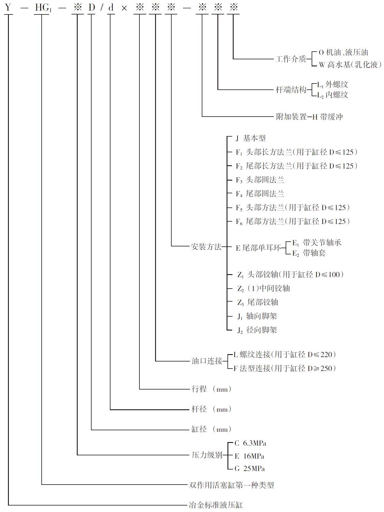
Model description
Features
-
Pressure:This standard cylinder is divided into two pressure levels of E/G. Class E is suitable for >6.3-16MPa (the hydraulic cylinder of this pressure range is called E-class cylinder); Class G is suitable for >16-25MPa (the hydraulic cylinder of this pressure range is called G-class cylinder).
-
Seal:The E-class cylinder uses a Yx-type seal with a simple structure and good wear resistance. The G-class cylinder is a V-shaped combination seal that is resistant to high pressure and reliable in sealing.
-
Dustproof:This hydraulic cylinder is made of polyurethane or butyl rubber without skeleton dust ring.
-
Applicable medium: hydraulic oil, mechanical oil, emulsion, not suitable for phosphate ester.
-
Applicable temperature: -40 °C to +80 °C, not suitable for low temperatures below -40 °C or higher than +80 °C.
-
Structure:This standard cylinder is equipped with 17 types of cylinder diameters(40、50、63、80、90、100、110、125、140、150、160、180、200、220、250、280、320)in accordance with two speed ratios to reach 34 stipulations.Divided into gap buffer and buffer structurewithout gap.The cylinder head and the cylinder tail can also have a one-way bleed valve, which can be used for quick start with a buffer cylinder and for deflation.The rod dust seal has a replaceable structure for on-site maintenance. The piston rod is coated with protective hard chrome, which is dust-proof, rust-proof, anti-corrosive and wear-resistant.
-
Installation connection: in line with the international ISO6020/1-1981 series hydraulic cylinder installation connection size.Basic types of different cylinder bores include, front and rear rectangle flanges, front and rear mounting flanges, front and rear round flanges, front, middle and rear hinge shafts, head single earrings, axial and radial tripods total 13 Installation forms.In addition to the axial tripod type, the dimensions of mounting connection are in accordance with I6020, 1-1981.
Ordering instruction
-
Pressure class E can be applied to working pressures of 6.3~16MPa.
-
In addition to the middle hinge shaft indicated specific dimensions, the rest can be filled according to the symbols on the table.The external connection dimensions can be referred to the table.
-
If gap buffer is required, please fill in the H match.
-
Please fill in the stroke according to the division in Table 4 of the stroke series.
-
For the working medium, applicable temperature, test, exterior painting, packaging, etc. of the hydraulic cylinder requirement, please specify.
-
The rod end earrings are customized according to users.
Technical specifications
缸径D、杆径d系列

注:表中*符号为ISO6020/1标准缸径D与杆径d,请优先选用。
油口系列

注:
1.此油口尺寸根据活塞油口最高流速V0(5m/sec)而定。
2.缸径D≥250,油口采用对开式法兰结构。
各种安装形式,在额定压力下的允许最大行程S(见表)其中
S1——头部法兰或轴向脚架安装,杆端带耳环;
S2——头部法兰或轴向脚架安装,杆端不带耳环;
S3——尾部法兰安装,杆端带耳环;
S4——尾部法兰安装,杆端不带耳环;
S5——尾部铰轴或尾部单耳环安装,杆端带耳环;
S6——头部铰轴安装,杆端带耳环;
S7——中间铰轴安装,杆端带耳环;
最大行程
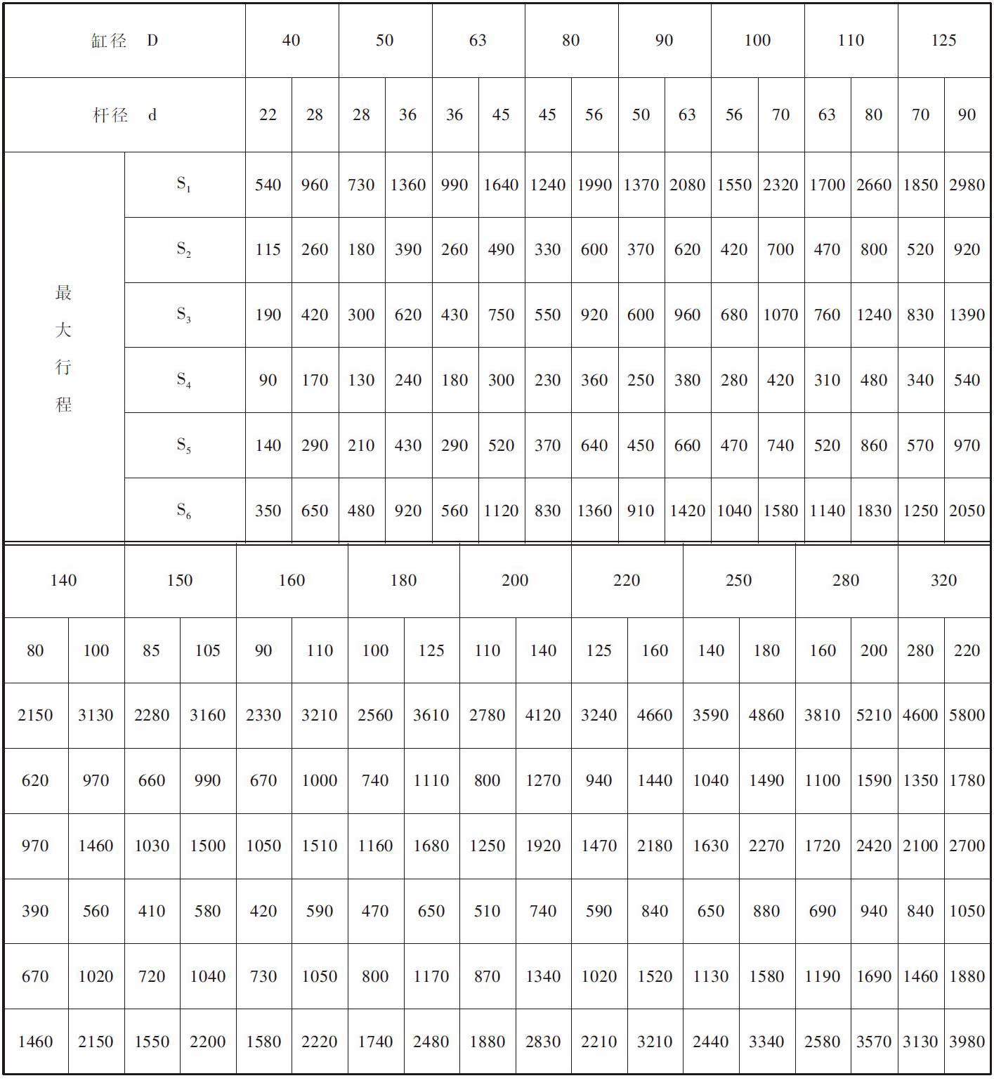
表中数字是按稳定性计算的最大行程,超了此表范围均为非标准,需设计者自行保证稳定性
行程系列

本系列采用ISO4393液压传动一缸一活塞行程的基本系列,请优先选用。
外形尺寸

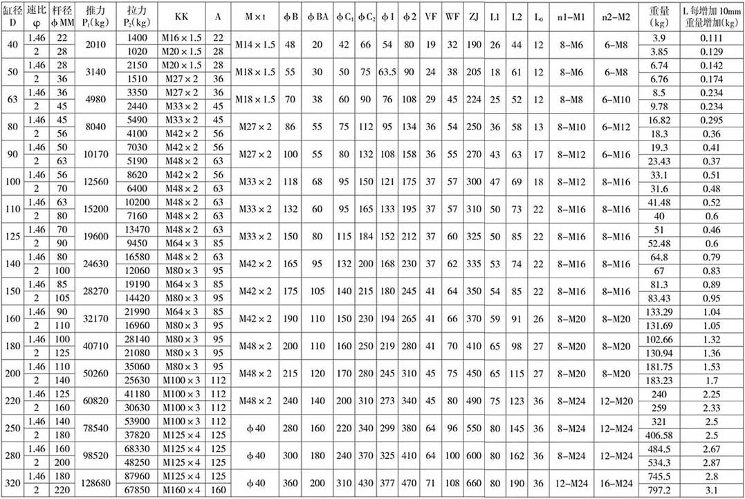
注:
1.选用液压缸时考虑管道阻力损失和机构中摩擦损失应将计算力加10%。
2.D≤20油口用螺纹连接,D≥250油口用对开式法兰连接,表中尺寸为油口通径。
头部长方法兰安装连接尺寸图表 Y-HG1 -ED/d x ※※F1 - ※L1※
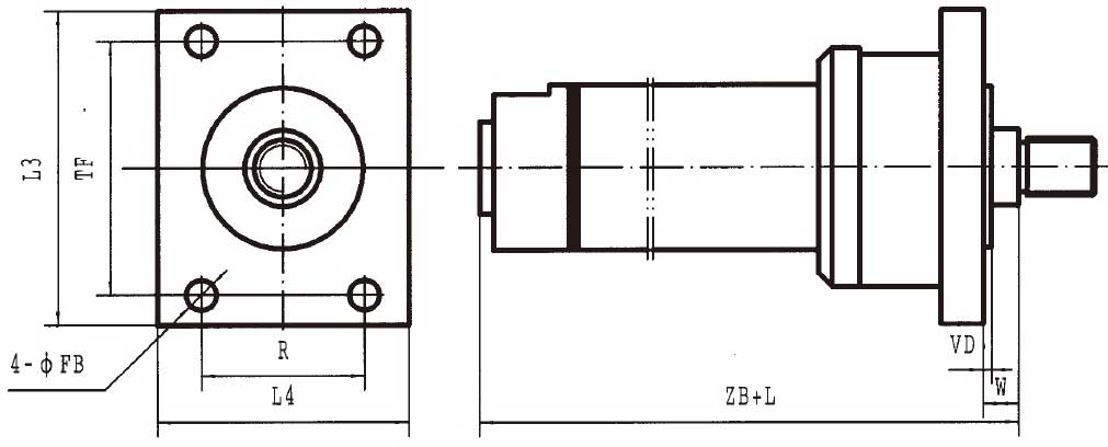

尾部长方法兰安装连接尺寸图表 Y-HG1-ED/d x ※※F2 - ※L1※
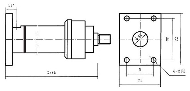

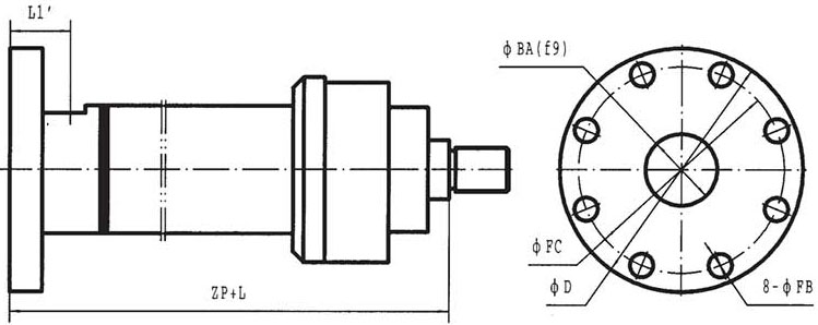
头部圆法兰安装连接尺寸图表 Y-HG1-ED/d x ※※F3 -※L1※
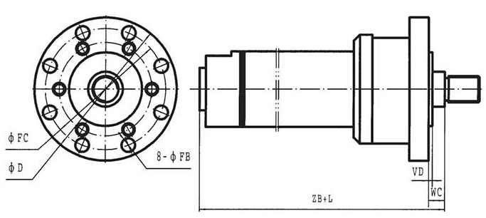

尾部圆法兰安装连接尺寸图表 Y-HG1-ED/d x ※※F4-※L1※

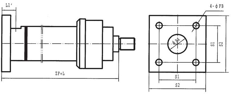
头部方法兰安装连接尺寸图表 Y-HG1-ED/d x ※※F5 - ※L1※
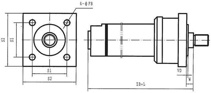

尾部方法兰安装连接尺寸图表 Y-HG1-ED/d x ※※F6 - ※L1※

尾部单耳环安装连接尺寸图表 Y-HG1 -ED/d x ※※E1*2 - ※L1※


头部铰轴安装连接尺寸图表 Y-HG 1-ED/D x ※※Z1-※※L 1※
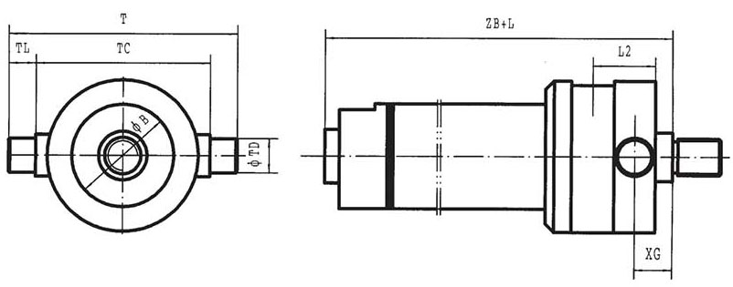

中间铰轴安装连接尺寸图表 Y-HG-ED/d x ※※Z2(1) ※L 1※
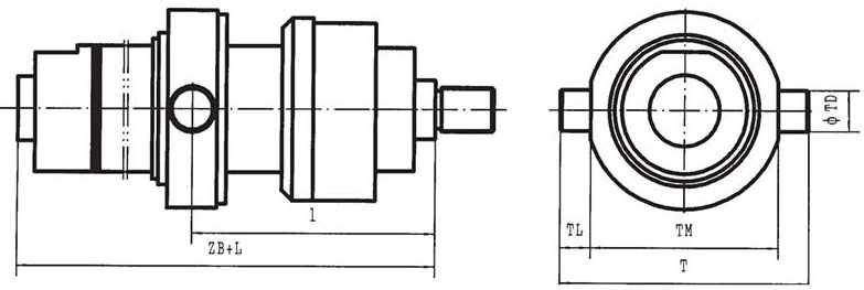

尾部铰轴安装连接尺寸图表 Y-HG1-ED/d x ※※Z3 - ※L 1※

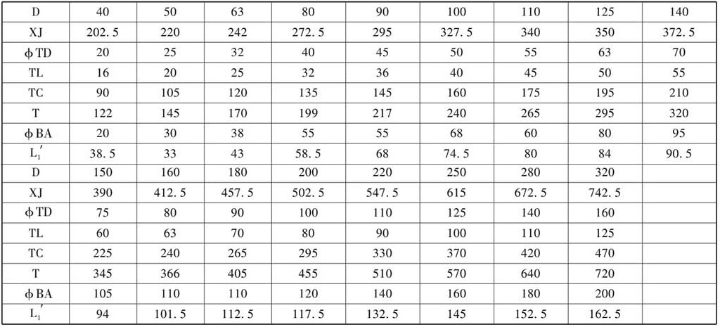
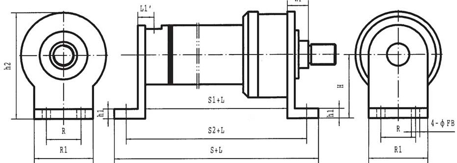
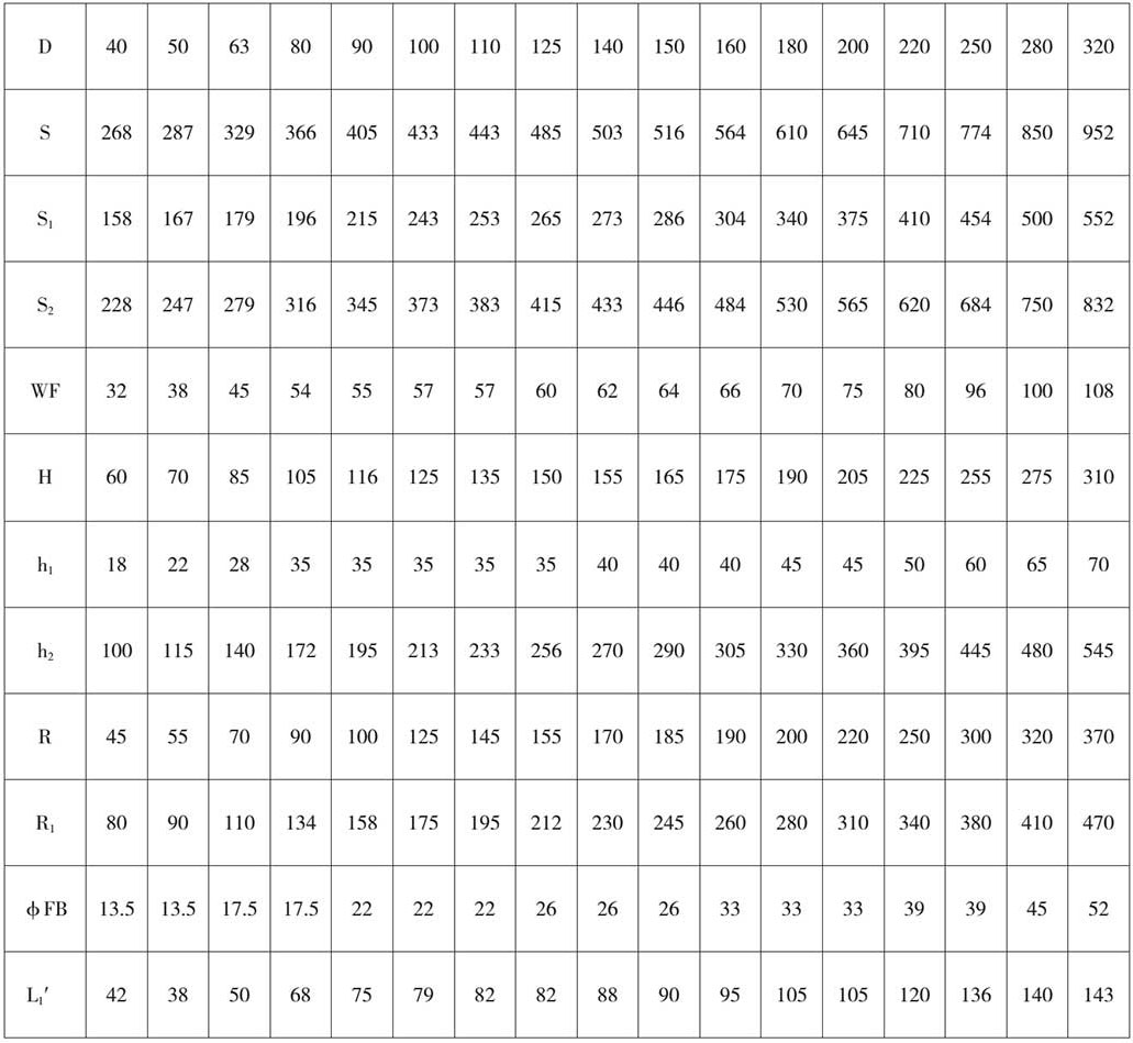
轴向脚架安装连接尺寸图表 Y-HG1-ED/d x ※※ J1 - ※L1※
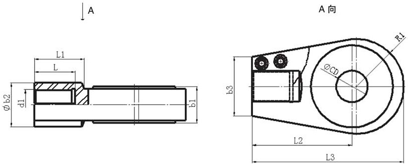
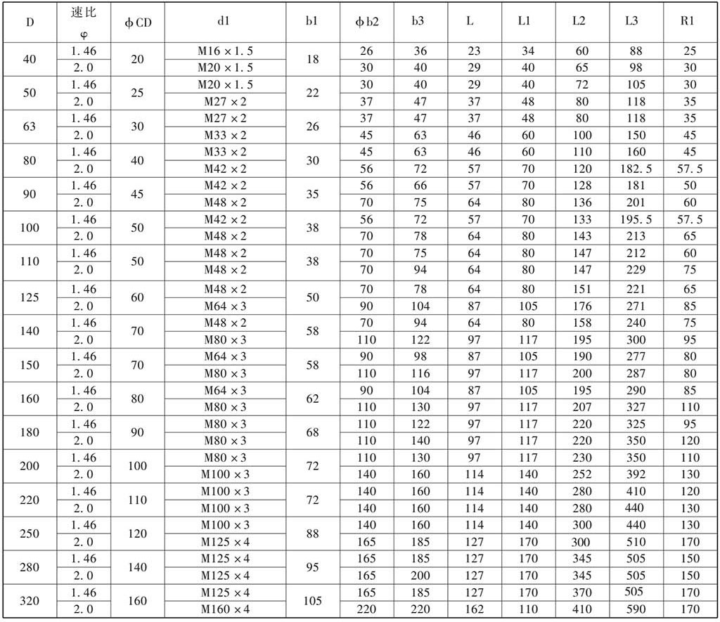
头部耳环连接尺寸图表 D/d GT-E1*2
Ordering instruction
1.When the heading earrings are selected for the smelting standard hydraulic cylinder, they should be ordered separately.
2.Earring number E contains two forms of E1 and E2. E1 is a joint bearing, E2 is a jointless bearing (with a bushing), and the installation dimensions are the same.
3.The cylinder diameter D and the rod diameter d should be indicated when ordering
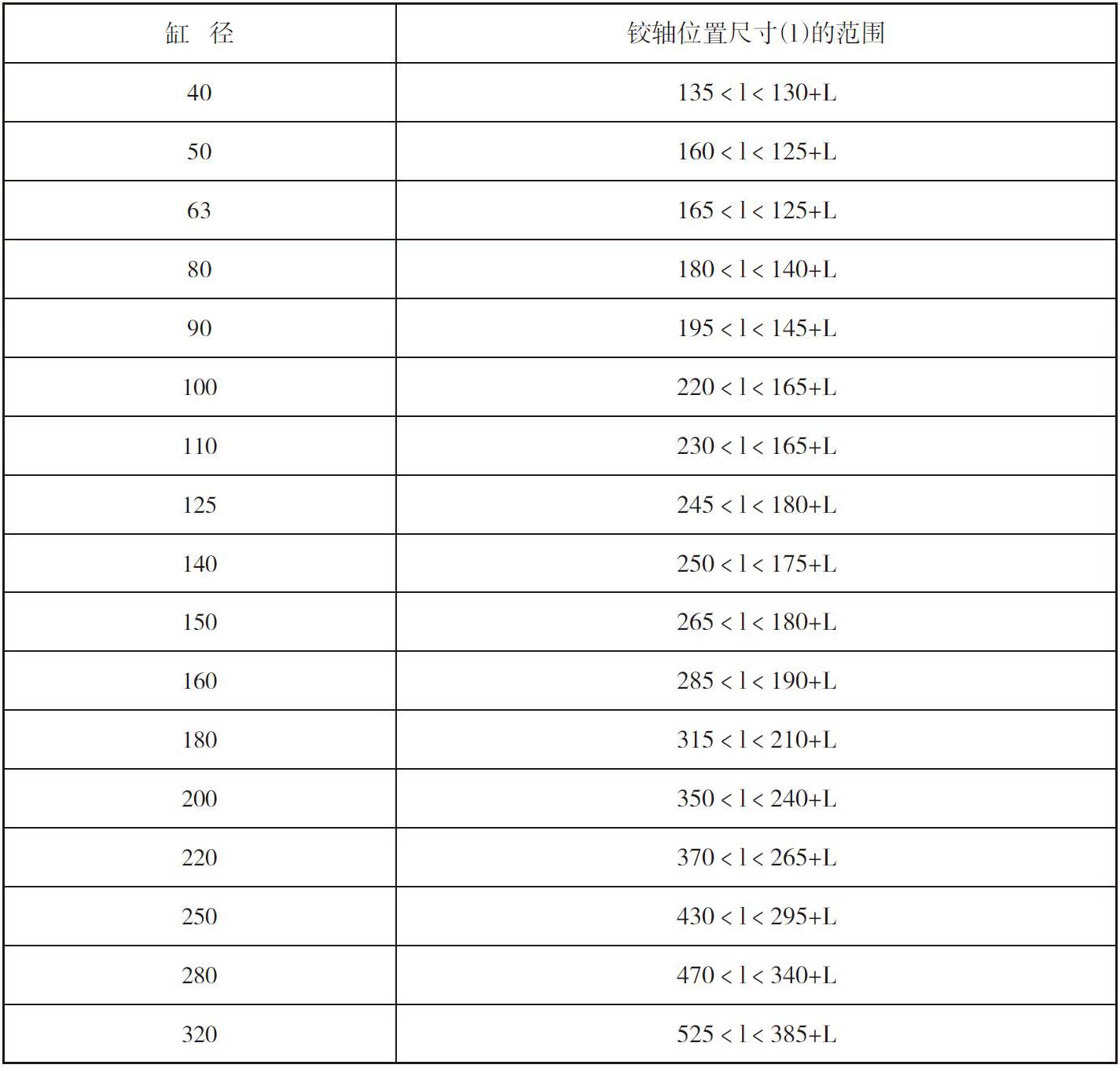
中间铰轴冶标缸
中间铰轴位置相对行程的关系见下表:
Instructions
1.The determination and selection of the cylinder bore, rod diameter and pressure of the hydraulic cylinder must take into account the pressure of the hydraulic system pressure source and the loss of the system. The pressure control and adjustment are determined by the hydraulic system pressure regulating valve.
2.Before the hydraulic cylinder is operated, it must be reciprocated several times with low pressure (higher than the starting pressure), and the one-way venting valve at both ends is alternately opened to remove the gas in the cylinder before normal operation can be performed. A combination seal must be fastened between the inlet and outlet ports to prevent hydraulic oil leakage.
3.In order to ensure the life of the hydraulic cylinder, the medium should not be mixed with impurities and dirt to avoid scratching the inner wall of the cylinder tank,causing damage to the seal and causing internal and external leakage.
 BAOSTEEL
 Dalian Heavy Industry
 Erasteel(France)
 China Electricity
 Jincheng Coal Group
 Jiugang Group
 Kungang Group
 Shagang Group
 Shougang Group
 TISCO Group
 Taizhong Group
 China Steel Group


