CY14 axial piston pump
CY14 axial piston pump
Video Display
Description
Property
CY14-1B axial piston pump
Introduction
CY14 axial piston pump is an axial piston pump with hydraulic oil distribution plate and cylinder rotation.Because of the hydraulic static balance between the piston shoes and the variable head and between the hydraulic oil distribution plate and the cylinder block, it has a simple structure, small volume, high efficiency, long service life and light weight compared with other types of pumps,self-priming ability and other advantages.It is suitable for machine tools, forging, metallurgy, engineering, mining and other mechanical and other hydraulic transmission systems.The pump only needs to change the motor hydraulic oil distribution plate or use it as a hydraulic motor.
Model description
|
Nominal capacity ml/r |
Variable form | pressure stage | pump/motor | type | Structure of the code |
|
turning direction |
|
1.25 2.5 5 10 16 25 32 40 63 80 160 250 400 |
M-rated S-Manual variable Y-Pressure compensating variable MY-Grading variable B-Electro-hydraulic proportional variable P-Constant pressure variable C-Maneuvering (servo) variables D-Electric variable |
pressure stage C refer to 31.5 |
Y-pump M-motor
|
|
|
B G为160、250CY 1500r/min Acc type |
turn direction(Look from the shaft end)
(clockwise) F refers to rotatry pump(anticlockwise) |
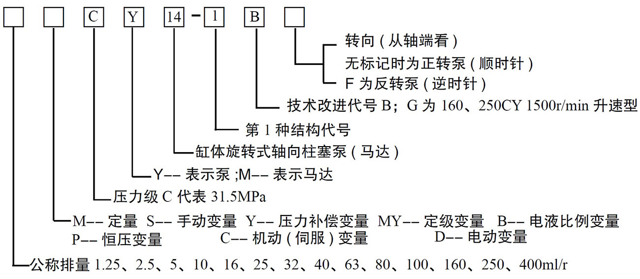
example:160YCY14-1G
A speed-up axial piston pump with a displacement of 160 ml/rev and a pressure compensation variable with a rated pressure of 31.5 MPa。(The nominal flow rate is 1000L/min at 1000r/min)
Recommended pipe or pipe joint size (non-reversible)
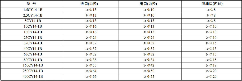
Note: The inner diameter of the drain port should not be limited by the size of the threaded joint.
serial model of pump
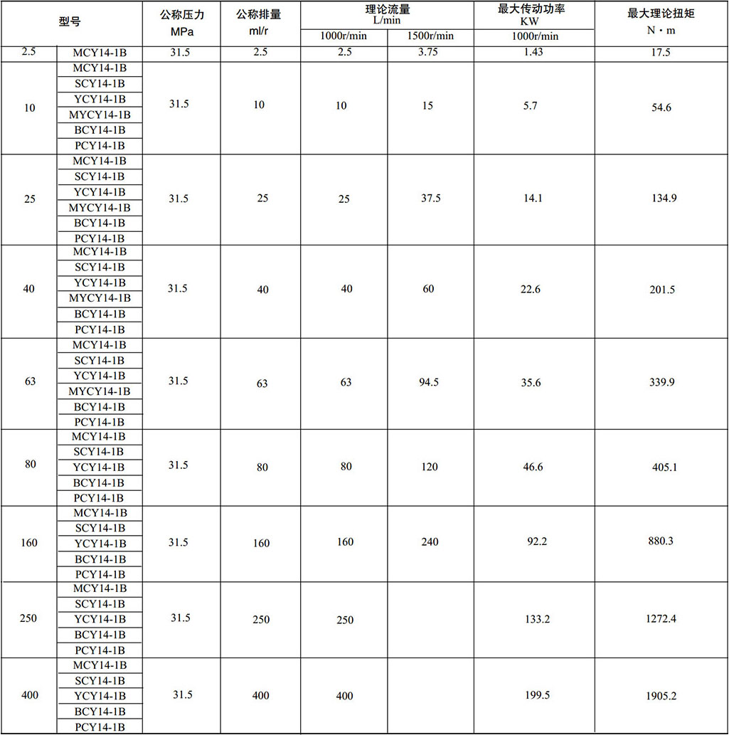
At a nominal pressure of 31.5 MPa, 1.25, 5, 16, and 32 ml/r displacement specifications are also derived.
Calculation of the actual power used by the pump
N=QP/(60η)(Kw) Actual motor power used
Q-flow rate L/min(Actual usage flow)
P-压力 MPa(Actual usage pressure)
η-total efficiency 0.85
The user can select the motor according to the actual load according to the formula above.。
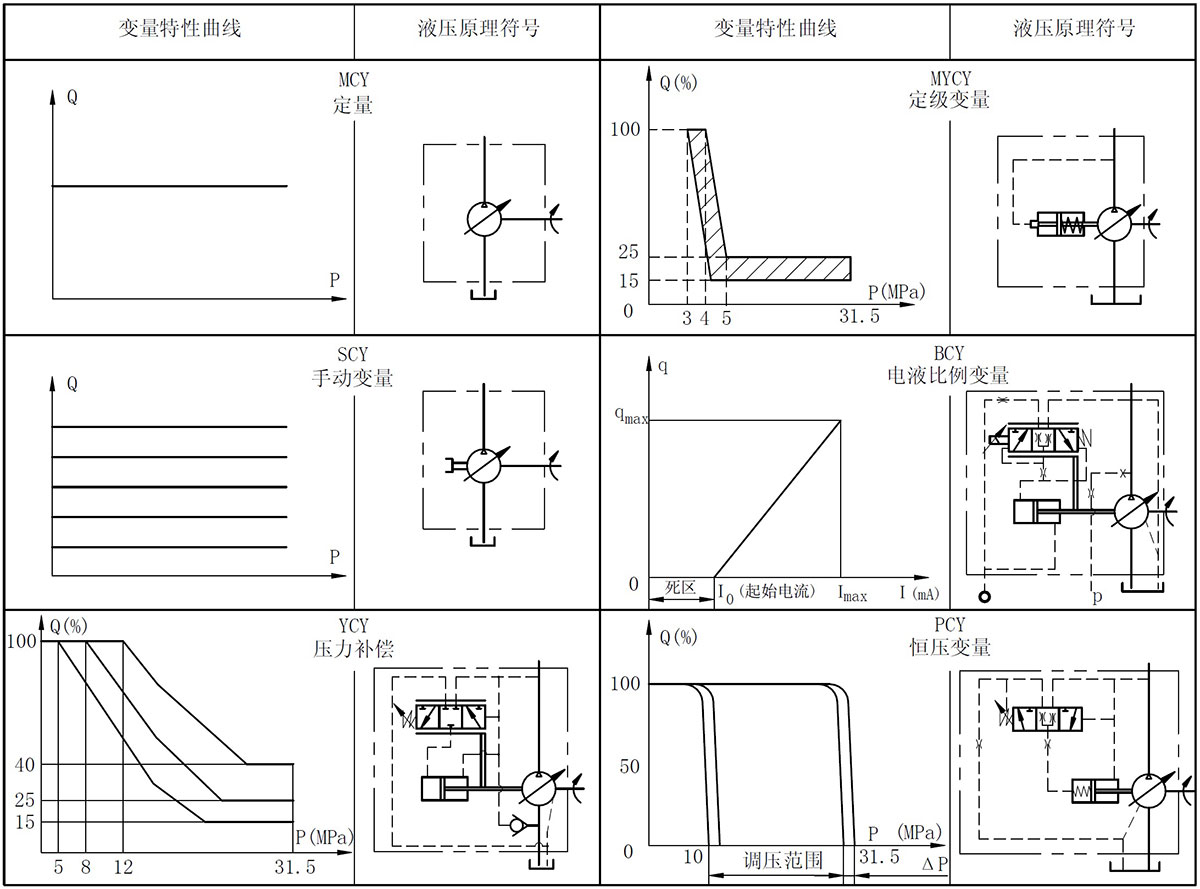
Hydraulic principle symbol and variable characteristics
Working principle and structure
The CY14 axial piston pump consists of two parts. The main part is equipped with various types of variable mechanisms to become various types of pumps.。
1、The working principle and structure of the main part
The main body part (see Fig. 1) is driven by the drive shaft to rotate the cylinder, so that the seven plungers evenly distributed on the cylinder body rotate around the transmission center line, and the sliding shoe in the column sliding assembly is pressed against the variable head through the center spring (or Swash plate). Thus, the plunger reciprocates as the cylinder rotates, completing the oil absorption and oil pressure action.
2、Working principle and structure of MCY14-1B quantitative pump
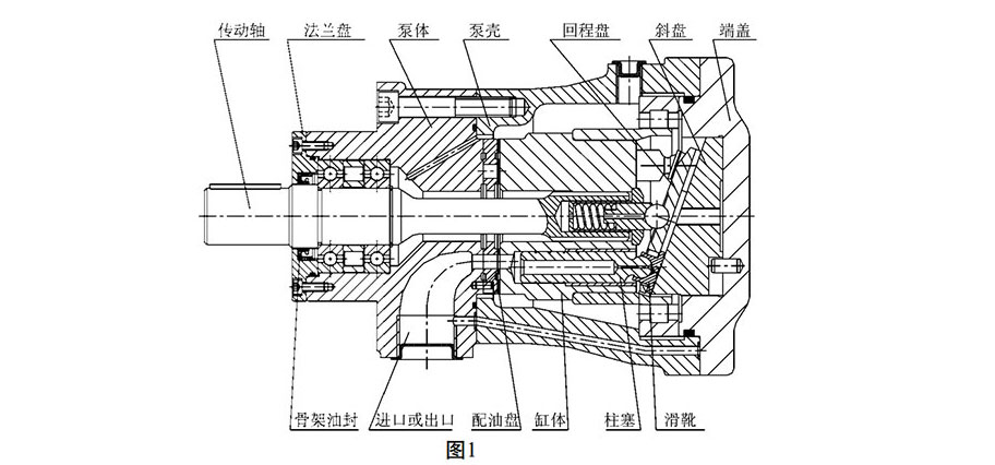
In the dosing mechanism, the swash plate is always fixed on the quantitative end cap, and the stroke of the plunger cannot be changed, so the flow rate is fixed. The pump only needs to be replaced with a grease pan or as an oil motor.。
Working principle and structure of SCY14-1B manual variable pump
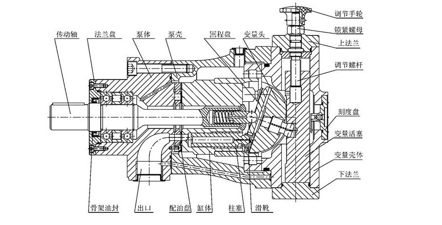
The manual variable pump changes the flow by external force to adjust the hand wheel, rotates the adjusting screw, drives the variable piston to move in the axial direction, and simultaneously drives the variable head to rotate around the center to change the tilt angle to achieve the purpose of the variable. The lock nut can be tightened when the required flow rate is reached. When the handwheel is adjusted to rotate clockwise, the flow rate is reduced. When the handwheel is turned counterclockwise, the flow rate increases. The percentage value can be roughly read from the dial. The flow must be unloaded during operation. If it is installed in the upper part of the fuel tank, the small yaw angle is not suitable for the self-priming of the oil pump.
Working principle and structure of YCY14-1B pressure compensation variable pump
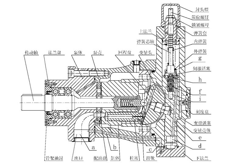
The outlet flow rate of the pressure compensated variable pump varies approximately in a certain range according to the constant pressure curve with the magnitude of the outlet pressure. When the high pressure oil from the main part enters the lower chamber (d) of the variable casing through the passages (a), (b), and (c), the oil enters the passages (f) and (h) through the passage (e), respectively. When the force of the spring is greater than the hydraulic thrust of the oil passage (f) entering the annular area of the lower end of the servo piston, the oil passes through (h) to the upper chamber (g), pushing the variable piston downward to increase the flow rate of the pump.。
When the hydraulic thrust on the annular area of the lower end of the servo piston is greater than the force of the spring, the servo piston moves upward to block the passage (h), so that the oil in the (g) chamber is relieved by passing through the (i) cavity. As the variable piston moves up, the variable head angle decreases, causing the pump flow to decrease.
When adjusting the flow characteristics, first screw the limit screw to the upper end, adjust the spring sleeve according to the required flow and pressure variation range, and the initial pressure when the flow starts to change, meet the requirements, and then screw the limit screw to the end. The flow rate at the stage pressure no longer changes, and the relationship between the flow rate and the pressure change is determined by the design of the pump itself.
Working principle and structure of MYCY14-1B grading variable pump
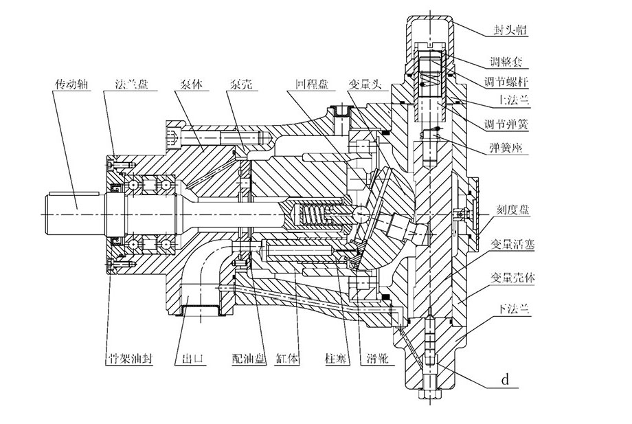
This type of pump relies on internal control (and external control) to manipulate the variable mechanism. The pressure adjustment range of the pump is relatively small, and after the oil pressure is generated at 3~4 MPa, the flow rate is rapidly reduced to the required high pressure flow value. This type of pump is actually equivalent to a high and low pressure combination pump. The pump power selection can be calculated by referring to the power selection method of the pressure compensation variable pump.
The high-pressure oil from the main part enters the lower flange (d). When the spring force is greater than the hydraulic pressure acting on the lower end of the push rod, the displacement piston is pushed downward to increase the flow rate of the pump. When the hydraulic pressure acting on the area of the lower end of the push rod is greater than the force of the spring, the variable piston moves upwards, reducing the flow of the pump.。
When adjusting the displacement characteristics, adjust the adjustment sleeve according to the required flow and pressure variation range, so that the flow rate at the final pressure of the pump does not change any more, and then adjust the adjustment screw so that the initial pressure meets the requirements when the pump flow rate changes.
Working principle and structure of BCY14-1B electro-hydraulic proportional variable pump
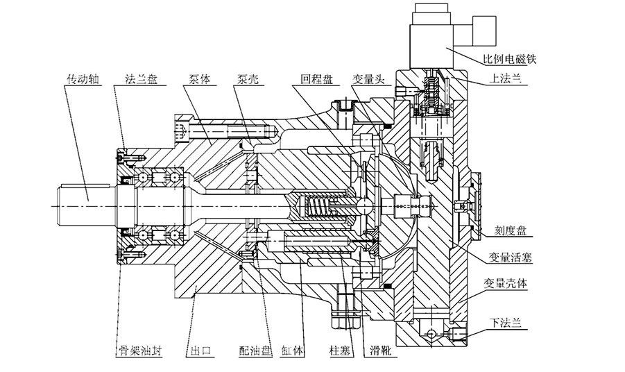
BCY14-1B electro-hydraulic proportional control variable pump is designed by the principle of “flow-displacement-force feedback”. It is a new type of displacement in CY14-1B axial piston pump, which is controlled by external hydraulic pressure. To control the displacement mechanism, and use the current of the input proportional electromagnet to change the flow of the pump, the input current is proportional to the flow of the pump. The pump has flexible control, sensitive action, high repeatability and good stability, and can easily realize remote control, automatic control, stepless speed regulation, tracking feedback synchronization and computer control of the hydraulic system, and is suitable for industrial automation requirements.
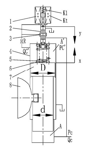
The working principle of the electro-hydraulic proportional control variable pump is as shown in the right figure. When the input current of the proportional electromagnet 1 is zero, the pilot spool 3 is pushed to the upper end by the feedback spring 6, and the externally controlled oil enters the variable piston 7 In the upper and lower chambers, since the upper chamber area A' is larger than the lower chamber area A, the variable piston is pushed to the lowermost position, the deflection angle of the variable head 8 is zero, and the displacement of the pump is also zero.
When the input current increases, the pilot spool 3 moves downward by the electromagnetic force, so that the upper valve port of the pilot valve is opened, and the upper chamber of the variable piston 7 is connected to the oil return chamber through the control side, and the upper chamber pressure is lowered. The variable piston moves upward, the variable head angle increases, and the displacement of the pump also increases. At the same time, the displacement of the variable piston acts on the pilot spool through the compression feedback spring, pushing the pilot spool to the equilibrium position, and the variable piston That is, maintaining a certain equilibrium position, the displacement of the pump is also maintained at a certain value. Conversely, when the input current decreases, the pilot spool moves upward under the action of the feedback spring, so that the valve port leading to the oil return chamber is reduced, and the valve port entering the upper chamber is increased, thereby increasing the upper chamber pressure Pc'. The variable piston moves downward until the electromagnetic force equals the feedback spring force, and the pilot spool returns to the equilibrium position, causing Pc' • A' = Pc • A, and the variable piston is again balanced at a new position.
When the input current is constant, if the variable piston moves up or down due to load or other reasons, the displacement change of the variable piston acts on the pilot spool through the feedback spring, changing the opening of the pilot valve to make the variable piston The upper chamber pressure rises or falls to resist the change of the load force, and finally the variable piston is returned to the position corresponding to the input current, that is, the displacement is kept unchanged.
It can be seen that the proportional variable pump can achieve proportional control of the displacement without interference from the load under the action of the input current. The main performance indicators of the BCY14-1B variable pump are: hysteresis H1 < 5%, repeatability HR < 3%, nonlinearity H LI < 5%, resolution true H1 < 2%, frequency response f-3dB > 1.5MHz ( 160/250BCY pump), f-3dB>3MHZ (25/63BCY pump).
The external control oil pressure of BCY14-1B pump is related to the working pressure of the pump. Under the rated working condition, the general external control pressure is recommended.
| model | 10BCY14-1B | 25(40)BCY14-1B | 63(80)BCY14-1B | 160BCY14-1B | 250BCY14-1B |
| External control pressureMPa | 4~6 | 6~8 | 8~10 | 10~12 | 12~15 |
If the working pressure used is low, the external oil pressure can be reduced accordingly.。
For the external oil supply, if the user requires the pump flow to be Qmax for t seconds, it is recommended that the external control pump flow rate is Q control > q/t (L/min), q see the table below.
| model | 10BCY14-1B | 25(40)BCY14-1B | 63(80)BCY14-1B | 160BCY14-1B | 250BCY14-1B |
| q(mL) | 44 | 55 | 66 | 83 | 118 |
Since the actual working conditions often do not require the flow to change between Qmax and 0, but vary from side to side at a selected flow rate, the actual required externally controlled pump flow can be greatly reduced.。
The starting current (dead zone) of the BCY14-1B pump is generally adjusted to 150~250mA, and the maximum control current is generally 650~800mA.。
The direction of the inlet and outlet of the BCY electro-hydraulic proportional pump is exactly opposite to the direction of the inlet and outlet of other variable-form pumps. From the shaft end, when the clockwise rotation (forward rotation pump), the inlet port is on the right side, and the outlet port is at Left side. In order to facilitate the commissioning during the factory test, it is best to use the reverse pump when designing.
Note: The BCY variable pump is at zero declination when there is no current input, so the angle should be adjusted before starting to prevent the oil pump from being damaged due to insufficient oil absorption.。
Working principle and structure of PCY14-1B constant pressure variable pump
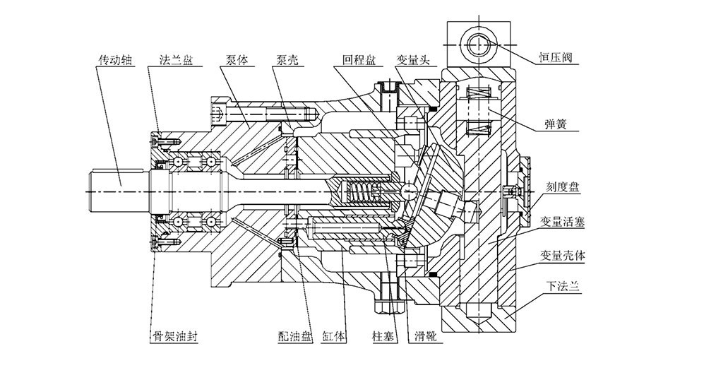
In this variable type pump, when the output pressure is less than the set constant pressure, the full displacement output pressure oil, that is, the quantitative output, automatically adjusts the pump flow when the output oil pressure reaches the set pressure to ensure constant pressure. , to meet the requirements of the system. The output constant pressure value of the pump can be steplessly adjusted within the pressure regulation range according to the needs. The structure of the pump is shown in the figure. The structure connects the output pressure oil to the variable piston lower chamber and the control oil inlet of the constant pressure valve. When the output pressure is less than the set constant pressure, the hydraulic pressure acting on the constant pressure valve core is less than the set spring force, the constant pressure valve is in the open state, the pressure oil enters the upper chamber of the variable piston, and the variable piston is pressed at the lowest position. The pump discharges the pressure oil at the full displacement; when the pump is working at the constant pressure, the oil pressure acting on the constant pressure valve core is equal to the set spring force, and the inlet and outlet ports of the constant pressure valve are simultaneously opened, so that the variable The hydraulic pressure of the upper and lower chambers of the piston is equal, and the variable piston balance works at a certain position. If the hydraulic damping (load) is increased, the oil pressure is instantaneously increased, the oil pressure port of the constant pressure valve is opened, the oil inlet is closed, and the variable piston is In the upper chamber, the lower chamber pressure is lowered, the displacement piston is moved upward, and the pump flow is reduced until the pressure drops to a constant pressure, at which time the displacement piston operates in a new equilibrium position. Conversely, if the hydraulic damping (load) decreases, the oil pressure drops instantaneously, the inlet port of the constant pressure valve opens, and the oil discharge port closes. The upper piston of the variable piston is higher than the lower chamber, and the displacement piston moves downward. The flow of the pump increases until the pressure rises to a constant pressure.
Shape and installation dimensions
1、Bracket shape and installation dimensions
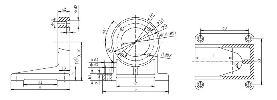
Note: Users can order the bracket with the corresponding bracket number according to the selected motor model, and indicate when ordering.
Bracket mounting dimension drawing

The 400CY stent is the same as the 25CY, the 80CY stent is the same as the 63CY, and the 400CY stent is the same as the 250CY. The brackets H0 and h are also different depending on the center height of the motor to be equipped. See the table below for details.

2、MCY14-1B dosing pump shape and installation size
The illustration shows the forward pump, and the reverse pump inlet and outlet are reversed.
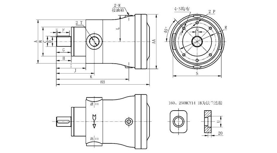
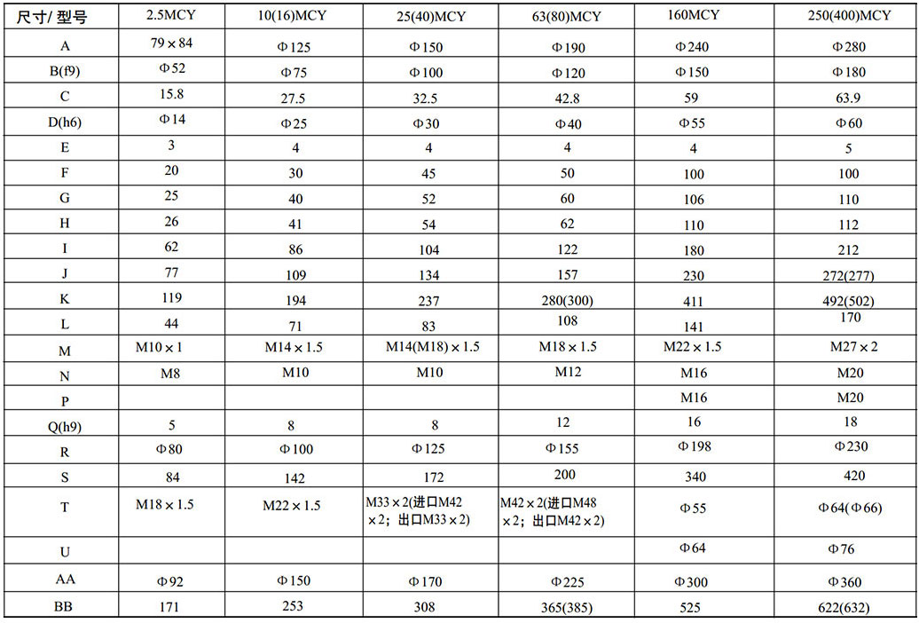
3、Shape and installation dimensions of SCY14-1B manual pump
The illustration shows a forward pump, which reverses the pump inlet and outlet.
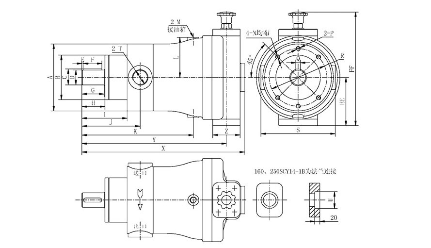
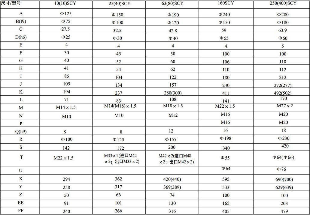
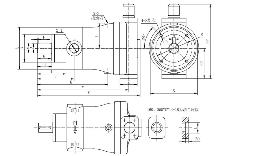
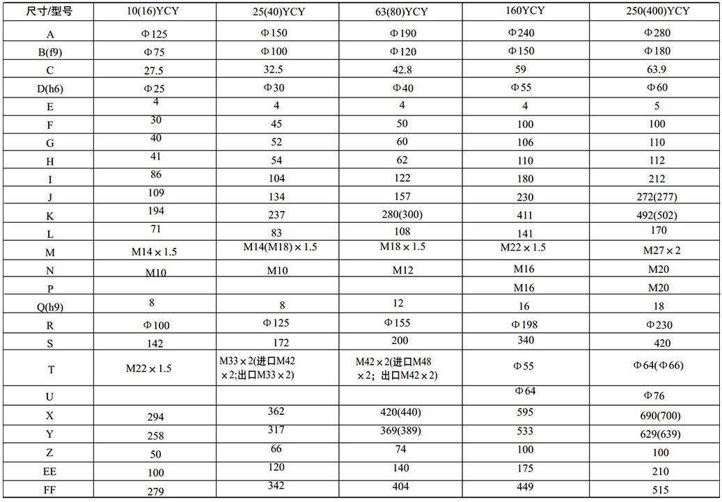
4、Shape and installation size of YCY14-1B pressure compensation pump
The illustration shows the forward pump, and the reverse pump inlet and outlet are reversed.
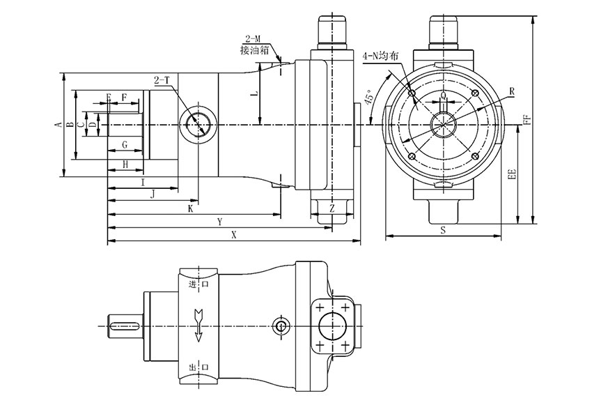
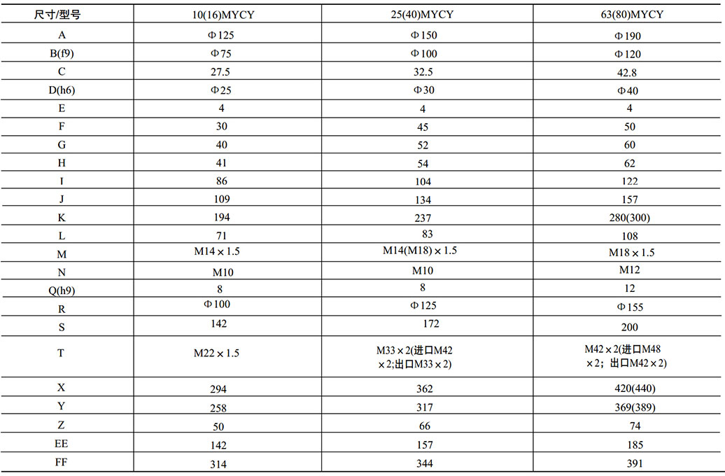
5、MYCY14-1B定级变量泵的外形安装尺寸
图示为正转泵,反转泵进出油口相反
6、Shape and installation dimensions of BCY14-1B electro-hydraulic proportional pump
(The illustration shows the forward pump, and the reverse pump inlet and outlet are reversed.)
(The direction of the inlet and outlet of the BCY electro-hydraulic proportional pump is exactly the opposite of the inlet and outlet of other variable-form pumps.)
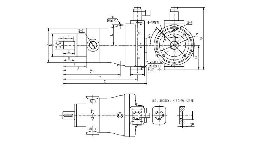
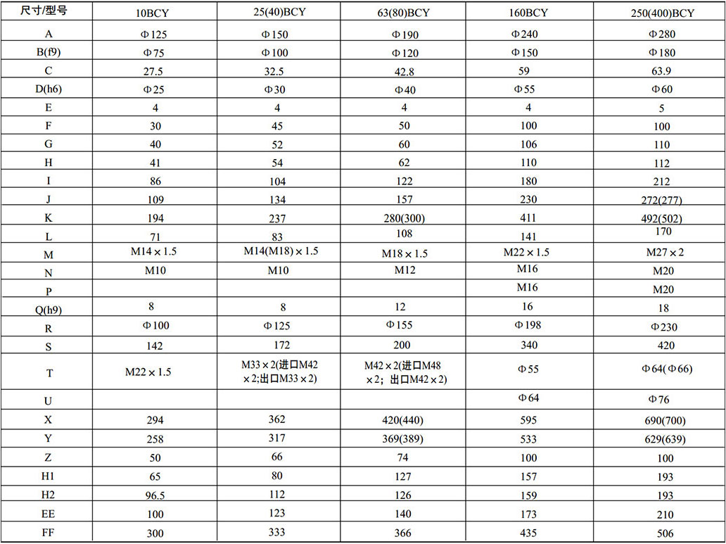
7、PCY14-1B constant pressure pump shape and installation size
(The illustration shows the forward pump, and the reverse pump inlet and outlet are reversed.)
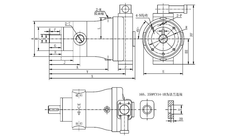
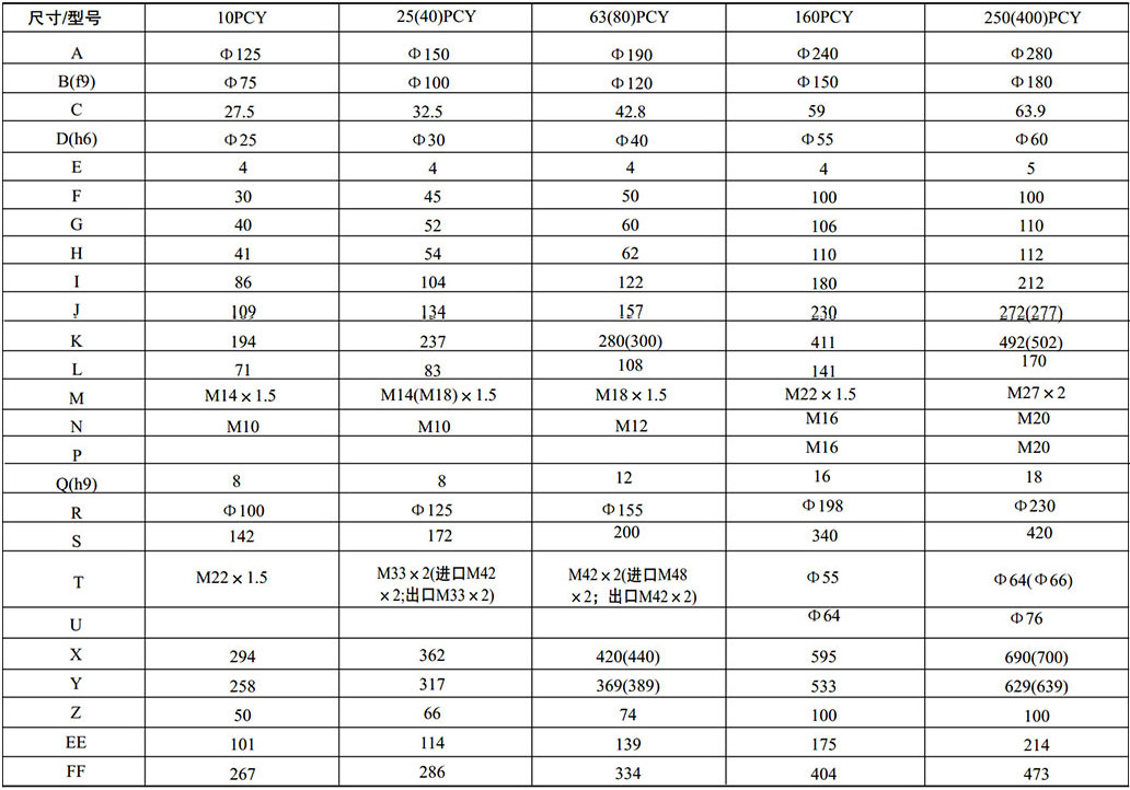
8、160CY14-1G speed pump shape and installation size
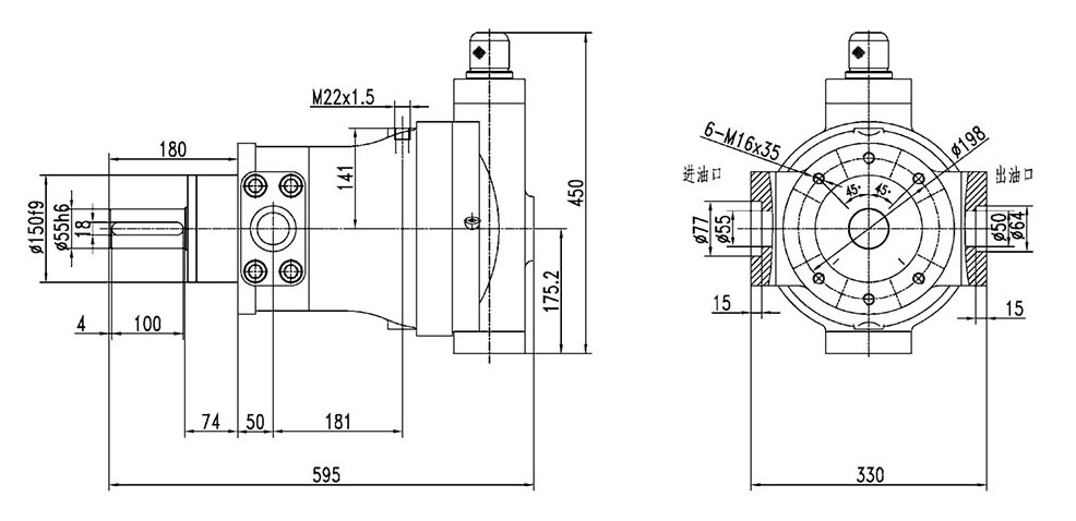
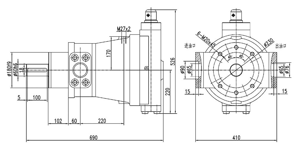
9、250CY14-1G speed pump shape and installation size
Case
 BAOSTEEL
 Dalian Heavy Industry
 Erasteel(France)
 China Electricity
 Jincheng Coal Group
 Jiugang Group
 Kungang Group
 Shagang Group
 Shougang Group
 TISCO Group
 Taizhong Group
 China Steel Group
Consulting
Telephone
Sales Department:0351-7038758/68
Sales Department:13703549773
Sales Director:13453466584
Pre-sales technical support:0354-3264078
Customer Services: 0354-3264079
HR Department:0354-8595117
International operational liaison service: 0351-7038778
Address
Shanxi Ocean hydraulic Co. Ltd
Address : No.9 road of Industrial Area, Yuci District ,Jinzhong City, Shanxi Province , China
Post Code : 030600
Website:http://oind.cn
E-mail:o@oind.cn
Address
Taiyuan Ocean Sega (High-Tech)Trading Co. Ltd
Address :1007,10/F Gaoxin International Plaza 227 Changzhi Road of Gaoxin Zone. Taiyuan City , Shanxi Province, China
Post Code : 030006
Website:http://oind.cn
E-mail:ocean@oind.cn

