Main feature
This component is a combination of a relief valve and an electromagnetic reversing valve to protect the pump and system.Electrical remote control via electromagnetic reversing valves for different functions.The pump and system can be unloaded or maintained and combined with the remote control valve to achieve 2 to 3 pressure control.
Model specification
|
F- |
A- |
S- |
BS |
G- |
-03 |
V- |
2B3A- |
A100 |
N |
51 |
|
Special seal |
With buffer valve note) 1 |
Low noise |
Serial number |
Bord connection |
Nominal size |
High unloading note)2 |
Oil drain form note)3 |
Coil symbol note)4 |
Electrical connection form |
Design number note)6 |
|
|
|
S:
Low noise
|
BS:
Electromagnetic overflow
|
G:
Bord connection
|
03 |
V:
Label only at high unloading |
2B3A
2B3B
2B2
3C3
3C9 |
AC:
A100
A200
A240
DC:Note)5
D12
D24
D100
The integer:
R100
R200 |
No mark:wiring box
N:
DIN socket |
51 |
|
F:
Label when using phosphate ester working fluid
|
A:
Mark when entering the buffer valve
|
06 |
|
10 |
Note)
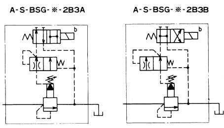
1.When using a buffer valve, it is only suitable for the oil draining type 2B3A, 2B3B. For details, please refer to the oil draining form.
2.Used to shorten the unloading to loading transition time
3.For details of the oil draining form, please refer to the oil draining form below.
4.The coil symbol is the same as the electromagnetic reversing valve DSG-01. Please refer to the DSG-01 standard electromagnet.
5.When the coil symbol "D*" is not indicated as "K", it actually includes the K series electromagnetic directional control valve.
6.Product design changes and design number without prior notice
When the design number is changed next time, the installation dimensions and performance parameters remain unchanged.
DC electromagnet is K series
The direct-acting K-series solenoid reversing valve can make full use of the characteristics of the DC electromagnetic reversing valve.
Parameter
|
Model |
Maximum operating pressureMPa |
Maximum flow rateL/min |
Pressure adjustment rangeMPa |
Qualitykg |
|
S-BSG-03-51 |
25.0 |
100 |
*~25.0 |
6.3 |
|
S-BSG-06-51 |
200 |
7.2 |
|
S-BSG-10-51 |
400 |
12.7 |
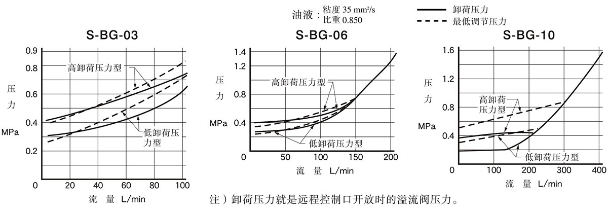
A low noise relief valve is used. Refer to the figure below for the minimum adjustment pressure and its characteristics.
The quality is double electromagnet(Hydraulic oil draining form
:3C2、3C3),Single electromagnet quality(Hydraulic oil draining form
2B3A、2B3B、2B2B、2B2)Subtract 0.6kg and add 1kg with buffer valve.
Flow-unloading pressure characteristics and minimum regulated pressure characteristics
hydraulic oil draining form
|
排油形式 |
JIS液压符号 |
电磁换向阀型号 |
电磁铁励磁状态与排油连接关系 |
|
SOL"a" |
SOL"b" |
排油连接 |
|
2B3A |
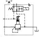 |
DSG-01-2B3A |
|
OFF |
与“A”口连接 |
|
ON |
与回油口连接(无负载) |
|
2B3B |
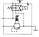 |
DSG-01-2B3B |
|
OFF |
与回油口连接(无负载) |
|
ON |
与“B”口连接 |
|
2B2B |
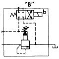 |
DSG-01-2B2B |
|
OFF |
关闭状态(溢流阀设定压力) |
|
ON |
与“B”口连接 |
|
2B2 |
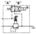 |
DSG-01-2B2B |
|
OFF |
与“A”口连接 |
|
ON |
与“B”口连接 |
|
3C2 |
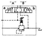 |
DSG-01-3C2 |
OFF |
OFF |
关闭状态(溢流阀设定压力) |
|
ON |
OFF |
与“A”口连接 |
|
OFF |
ON |
与“B”口连接 |
|
3C3 |
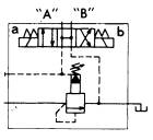 |
DSG-01-3C3 |
OFF |
OFF |
与回油口连接(无负载) |
|
ON |
OFF |
与“A”口连接 |
|
OFF |
ON |
与“B”口连接 |
可选择
带缓冲阀:排油形式2B3A,2B3B型电磁换向阀与溢流阀之间带上缓冲阀,使设定压力向卸荷状态过渡时,压力缓慢下降,防止回路冲击。 卸荷压力与缓冲阀无关。
Base plate
|
Model |
base plate type |
dia.Rc(formerPT) |
W.kg |
|
BSG-03 |
BGM-03-20 |
3/8 |
2.4 |
|
BGM-03X-220 |
1/2 |
3.1 |
|
BSG-06 |
BGM-06-20 |
3/4 |
4.7 |
|
BGM-06X-20 |
1 |
5.7 |
|
BSG-10 |
BGM-10-20 |
1 1/4 |
8.4 |
|
BGM-10X-20 |
1 1/2 |
10.3 |
When using the base plate, please order according to the above model. When the base plate is not used, the valve mounting surface accuracy: flatness 0.013mm, roughness 0.0016mm.
The base plate is common to the pilot relief valve. Please refer to the pilot relief valve base plate.
Attachment
mounting screw
|
Model |
soket head cap screw CB70-85 |
|
S-BSG-03 |
M12x40 4 pcs |
|
S-BSG-06 |
M16x50 4 pcs |
|
S-BSG-10 |
M20x60 4 pcs |
Precaution for use
Use the remote control relief valve to refer to the remote control relief valve at the remote control port.If the internal volume of the remote control port is too large, vibration is likely to occur, so the inner diameter and the length of the pipe should be minimized.
When adjusting the pressure, first loosen the lock nut and turn the handwheel clockwise to increase the pressure, otherwise the pressure is reduced.Every revolution of the handwheel, the pressure changes about 5MPa. After setting, the lock nut must be tightened.
The pressure adjustment is limited by the gasket. When the pressure is not reached, remove the gasket, each gasket is about 10 MPa.
The piping in the return hydraulic oil tank must not be connected to other valve return pipes, but should be returned directly to the tank.
When the flow rate is small, the set pressure is unstable. Flow rate should be above 5L/min
 BAOSTEEL
 Dalian Heavy Industry
 Erasteel(France)
 China Electricity
 Jincheng Coal Group
 Jiugang Group
 Kungang Group
 Shagang Group
 Shougang Group
 TISCO Group
 Taizhong Group
 China Steel Group


